Temperature Controls Final Solution
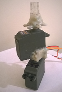
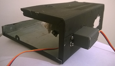
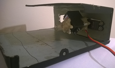
March 24th, 2015

The new servos had arrived so now I could try and get this part of the project finished at last. This method was a bit trickier to implement because it involved attaching two servos together. The second servo is needed to turn the first servo that extra 70 degrees. The image to the right shows both servos glued together. A frame also had to be made to mount the rear servo onto. The images below shows the frame with the two servos bolted on.

2servo
frame1 frame2

With the servos now secured on the frame, the control mechanism could now be set in place. Now that the mechanical side was almost complete I tested the controls using the UI. When the Arduino starts up it reads the temperature inside the car using the temperature sensor attached to it. For example, if the driver sets the desired temperature to 26 degrees but the temperature inside the car is only 19 degrees then the temperature setting control will begin turning from cold to hot and the fan speed will be set to full speed. When the temperature comes within 3 degrees of difference the fan speed will then decrease and when the temperature inside the car overshoots the desired temperature the temperature setting control will the begin turning from hot to cold. This will repeat until the inside temperature comes to within 1 degree and by that stage the temperature setting control should be set in the correct location.

end of tempaltemo_content

FM Radio

March 16th, 2015

After getting the temperature control UI together in so form I the new servos had still not arrived so I made a start on getting a user interface together for the radio. This must to be able to store a number of preset radio stations and also allow the driver to change the current station to a frequency of their choice and then add that station to one of the presets.

radioUi

By pressing the arrows left or right the frequency will then increase or decrease. The frequency can also be changed by dragging the slider to the desired frequency. To save this frequency to one of the presets the user must hold whatever preset the want to put it in for 2 seconds. The frequency will then appear in this location.

After getting the UI together the hardware side now had to be looked at. I had ordered a FM radio chip for the Arduino a couple of months ago so it just needed to be connected to the Arduino. Turns out the chip was smaller than I had expected and soldering the wires to the chip was a bit of a challenge.

radioChip1
ArduinoRadio

With the chip now connected to the Arduino I then found a library to use with this chip at http://playground.arduino.cc/Main/TEA5767Radio. Using this library I was able to get the radio up and running quickly and by adding a potentiometer the frequency could then be changed without hard coding it in the code. The next task was to link the radio to the UI but this is going to be a job for another day….

Temperature Control UI

March 3rd, 2015

While waiting on the new servos to arrive I made a start on the temperature control user interface. The interface should allow the driver to set the desired inside temperature and the temperature inside the car should eventually rise or fall to that temperature. When the driver sets their desired temperature on the left then the fan should start up and the servos should them adjust the temperature controls accordingly. The fan speed setting should allow the user to take control and reduce the fan speed if they think it is too noisy. The temperature should still adjust to the driver’s desired temperature but just at a slower rate now. The controls to the right will allow the driver to set the blower direction to direct air towards the windscreen or to their face. I plan to improve the design of these controls but for now it will do the job I need it to do.

temperatureControls

Arduino Temperature Control Solution

February 25th, 2015

So much time was wasted on this part of the project now that I really wanted to give up on this and move onto some other part but that can’t be done. This is about the only part of the project that must be fully completed and be reliable because it will not be accessible once the screen is installed.

I came up with yet another idea to attempt to solve this problem. That is, to have four 180 degree servos do the job instead of the two 360 degree servos. The advantage to this solution is that we will know exactly what position each control is at without any other switches or potentiometers thanks to the 180 degree servo. The problem now was that I had to order 4 new servos meaning a delay of at least another week….

Arduino Temperature Control Coding Problems 2

February 20th, 2015

I spent a while thinking about another solution and then came up with this one involving micro switches. First I removed the potentiometers and the for the blower direction I glued 4 micro switches to the control mechanism and made a ridge on one of the servo tops. Now when the servo turns, the ridge on the servo will trigger one of the switches. For example, if the air is being directed towards the floor and I want to change the blower direction to blow the air to the windscreen then the servo needs to turn 90 degrees clockwise. The servo will turn until it breaks the switch at the top that’s for the windscreen.

servoMicroswitches

The wiring diagram below shows how the servo receives signals from the Arduino pins and how the switch then cuts the signal when pressed. In the diagram switch S2 is open because the ridge of the servo is against it therefore no signal/power gets through the switch to the servo meaning the servo should stop. Meanwhile, all the three other Arduino pins which are live are sending the value of 100 to the servo which should signal it to stop.

switchDiagram1

Once again this method was a failure. Thinking about this now afterwards, I have a feeling the three pins that are sending the stop signal to the servo may be scrambling the signal that it should be receiving but I have no proof of this so it is a mystery to me what the problem is!

Arduino Temperature Control Coding Problems 1

February 12th, 2015

Now that the servos were ready to be attached to the temperature control mechanism the Arduino code needed to be written to control the movement of the servos. Since these 360 degree servos continue to rotate until they are told to stop we need to know the position of the servo. To do this I glued a potentiometer to the end of the servo. Now when the servo turns the potentiometer turns. Using the Arduino we can read the value of the potentiometer then map this value to the range of 0 to 250 degrees. This then gives us the exact angle of the servo. Having this information allows us to tell the servo to stop turning when the angle reaches 0 degrees or 250 degrees.

servoPot

It was now that the bugs started to occur and I can only assume that it is a fault in my coding. The servo would turn fine but sometimes when it reached 0 or 250 degrees it wouldn’t stop turning. It just seemed like the Arduino wasn’t processing fast enough to call the stop function when the servo reached the max or minimum value. After spending days looking for a solution I felt it was time to look for another way……

Modifying The Temperature Controls

February 6th, 2015

Having all the bits I needed, it was time to make a start. The first task was to discover how the 360 degree servos worked. Unfortunately they did not work the same as the standard 180 degree servo. To turn the 180 degree servo the value in degrees is sent from the Arduino to the servo object using the servo library. So sending the value of 110 from the Arduino to the servo would result in the servo moving to 110 degrees.
The 360 degrees servo acted a lot different. First I noticed a screw buried on the side of the servo and of course, I screwed it a bit but later found that it was best left alone. Setting this screw/potentiometer in the center seemed to work the best. I the value of 100 was sent to this servo it would stop but when the value of anything above 100 is sent it turns, increasing in speed as the value increases. Sending a value less than 100 resulted in the servo turning in reverse and likewise increasing in speed as the value gets lower.

Now that I knew how to control the servo the next problem was getting the servo to turn the knobs. The best method I could see was to remove the center piece from the knobs and stick them onto the servos. Getting this center pieces removed proved to be harder than I thought! The pliers were unable to pull it out so I then went for the heat gun to try melting it around the edges to loosen it. Eventually it came off but was very rough looking. For the other two I just cut them with the hacksaw and they turned out ok. The next job was to stick them onto the servos. I had order epoxy glue at the same time as the servos for this job. 10 minutes later the epoxy had set and the servo looked well!

heat
hacksaw
epoxy servoEpoxy

Gathering Parts For Modifying The Temperature Controls

January 29th, 2015

To modify the temperature controls I first found a set of suitable servo motors and got them ordered. I knew that it would take a fair amount of torque to turn the knobs so luckily enough the servos I had found were capable of applying 6kg of pressure so I hoped that would be enough. Because the controls for the temperature and blower direction turned from 0 to about 250 degrees the standard servos would not be suitable for the job because they only move from 0 to 180 degrees. Luckily enough there were 360 degree servos available too.

Turnigy6kg

While waiting for the servos to arrive I went to the local breakers yard and got another one of the temperature control mechanisms. This meant I could modify this one and then swap it with the one in the car when the time came to install it. With more than 4 different models of this part available I was very surprised when I found the one with the exact same part number as my own in the very first car I looked in!

tempControl

Temperature Controls

January 23rd, 2015

I have planned to install the system in the car as soon as possible to get as much of the hardware problems out of the way so I can focus on the software side of the project. The final restriction that is holding up the installation is the temperature control settings that allow the driver to adjust the heat inside the car. As the screen take up most of the center area of the dash these controls will have to be moved and the only other suitable place for them is behind the screen. Doing so now means the driver cannot manually adjust the fan speed and blower direction by moving the knobs. To overcome this problem the plan is to push the controls behind the screen and have servo motors move the knobs when instructed by the driver. There will be a suitable user interface on the screen which allows the driver to select the desired temperature inside the car and with the use of an Arduino, a few servos and a temperature sensor the temperature should gradually change to the driver’s desired temperature. The image below shows the current setup in the car and you can see how the temperature controls are in the way.

Current

Redesign The Home Screen

January 19th, 2015

With the media player and parking assist now in some way functional I am fairly confident that they can be improved and made to work reliably. I have now decided to try making some improvements to the design of the home screen.

First to explain why I used the simple design. The retro styled buttons may look ok in my car but no media players that I have ever seen use this kind of design. The idea of the buttons was to keep with the theme in my car with the main colors being blue, red and black. The reason for this for this basic design is to make the system look as if it could have come as standard with the car when it left the factory rather than look like most modern stereos that just look out of place in older vehicles with their modern look and feel. Most of the time an aftermarket stereo in an older vehicle could be spotted a mile away. Older stereos tend to have very few buttons but the few that were available were clearly seen and their function was usually fairly obvious. Modern stereos tend to have quite a lot of small buttons and often many of them have more than one function, making it very confusing. I planned to keep the home screen as simple as possible with just a handful of buttons. The buttons were designed to copy the dashboard theme which has the blue LCD for the odometer with the black text. The analog clock in the center uses the same theme as the speedometer with the red dials and blue marks around the edge.

OldHomeScreen

The new design seen below may suit a more modern car ok but it is clearly visible that there is no way that this could have come as standard in my car so and extra possible feature could be to allow the user to choose different skins to suit their vehicle but for now I just decided to go with a more modern design. To modernize the buttons I added suitable images to accompany the text and also added shadow and glow effects. The analog clock may not look much more modern yet. The background is also changed from the solid black colour to a glowing effect behind the clock that radiates light to about half of the screen. Improvements are needed but for now this will have to do…….

homeScreen

Parking Assist

December 29th, 2014

The only function the system has at the minute is a media player so I think it’s time to begin working on another useful function. A reversing camera that could show the driver the distance to the nearest object and give off a beep to alert the driver as they get closer to the object would be a useful feature. To do this I am using an Arduino along with an ultrasonic sensor to detect the distance and a USB webcam connected to the laptop motherboard. The Arduino gathers the information from the sensor and sends this data to the WPF application over the serial connection. The distance will then be displayed on the LCD on top of the video feed from the camera. At the minute this setup is functional but improvements may need to be made to help with object detection such as narrow bollards at either corner of the vehicle in the driver’s blind spot. We cannot rely on the one ultrasonic sensor being used at the minute so one or two more sensors may need to be added to make the setup fully functional.

A Different Approach To Get The Information

December 15th, 2014

After another couple of hours scanning the internet I came across a small device called MPGuino that was designed to monitor a vehicles fuel consumption and calculate the miles per gallon using the Arduino platform on vehicles before the OBD-II era. These devices were quite hard to find so instead I just downloaded the schematic (below) and made my own.

MPGuinoSchmatic

The schematic was fairly straightforward but it took quite a while to get the device assembled. It connects to the car using only 4 wires, +5volt, Ground, Vehicle Speed Sensor (VSS) Lead and another wire that connects to the Injector Ground lead. Since the Arduino Uno board is quite big I decided to assemble an Arduino (still using the same 328p-pu chip as the UNO) and add the MPGuino components all to the one board. This resulted in a more compact device as seen below.

MPGuino

With the MPGuino now made the next task was installing it in the car. Once again this was not a simple task because the device was designed for older vehicles with one wire connected to a fuel injector. Unfortunately my car was not so straightforward because the injector ground lead did not carry the correct signal. After more online research it looked like these signals could be read directly from the ECU. With so many ECUs available for the same year and model of car finding the correct pinout diagram was another mission. I found what I though was the correct one (or near enough/ most of the wires in the same place) and then removed the ECU from the car and joined the VSS and injector gound (Fuel consumption) lead to what I hoped was the correct wires.

ECU

So with the wires all connected and inside the car it was time to test the MPGuino. I connected the power and it booted up and all looked well. I started up the engine and went for a short run. The device looked to be working ok but when I stopped and checked the collected readings the values were way off. After a couple of hours following online forums to configure the device I then assumed that the wires must be connected the incorrect wires on the ECU. With no official pinout diagram for the ECU I was now lost. With so must time put towards researching, building and wiring the MPGuino I really didn’t was to just forget about it but at this stage there really was no other option if I wanted to get the project any way presentable for January.

Get Feedback Attempt Two

November 26th, 2014

The new OBD cable has arrived and didn’t seem to make any difference. When I ran Vag-Com again I noticed a button on the home screen called “OBD-II” that would test if the vehicle is OBD-II compatible. This was a sad moment!  I now know that the car is not OBD-II compatible so what I thought would be a simple task of reading the information from the ECU might not be doable (by me anyway).

Vag-Com

Get Some Feedback From The Car

November 19th, 2014

The next task now is to have a go at getting some of the values from the cars ECU through the diagnostics port. I found a library online at: https://www.nuget.org/packages/Coding4Fun.Obd.ObdManager
I have written a console application to test with this library that should ask the ECU for the engine coolant temperature and then print this to the console screen. For some reason the connection to the OBD fails. I find this strange as the very popular VW Audi diagnostics software Vag-Com works fine. Various forums online mention that an aftermarket stereo can cause this problem so I’ll try this solution first. If that doesn’t solve it I have a feeling it could be a problem with my cable so I’ll try a new cable then.

The LCD Arrives

November 16th, 2014

So the laptop has arrived. I had the hard drive ready to set in and install windows to get the laptop up and running before removing the screen to be sure that the finger touch screen worked ok. Yet another problem. It’s the first laptop I ever saw with a 1.8” micro SATA drive. So that means my 2.5” drive isn’t going to fit. With a SATA to Micro SATA adapter now on the way I’m hopeful that the touchscreen will work as it should. With the screen now removed I had a go at fitting it. After late night/early morning but luckily it seems to just about fit.

raspberry-pi-rev2

Plan B

November 14th, 2014

After explaining this problem to my project supervisors they had suggested coming up with a plan B in case the idea of having a Pc in the car running a WPF application becomes more difficult than I had thought. The idea that was suggested involved using a raspberry Pi running the Linux OS and using an existing media player application. This idea if successful would save a lot of time and effort because the raspberry Pi could be fitted behind the LCD saving the need to have a Pc in the boot. Again the problem of the 12” LCD comes up but this idea will be used if the major problems are found with running the Pc and WPF application!

raspberry-pi-rev2

Resolving the LCD Problem, Second Try

November 8th, 2014

As time was now starting to get shorter the decision had to be made on an LCD. After searching online I found that Dell have made a tablet laptop with a multi-touch 12.1” LCD. I then found a grade C model on eBay for a reasonable price. There are a few problems with it though. The case is badly damaged, it has no hard drive and very little Ram. Luckily these are not major faults and this sounds like the ideal laptop for this project. The damaged case would have no effect because the screen and motherboard will have to be removed from the case to make it fit properly. I had planned to use an SSD hard drive anyway so this would have more than like been replaced and finally the RAM problem is not issue either because of the WPF application running on it is very unlikely to be that intensive. With the laptop now in the post the waiting game begins……

What About The Hardware

November 3rd, 2014

With the application now starting to show some signs of coming together I thought I had better face the major hardware problem that has pushed aside since. This being the screen problem. After accepting that it is going to be very unlikely that the screen I recently got will work, a new idea is needed. One idea would be to buy a new multi-touch laptop or tablet and the other would be to get a smaller touchscreen that would fit into the space with no problem. The problem with these ideas is that the laptop will be slightly expensive and the smaller screen would not offer much of an upgrade from the 7” LCD currently in the car. This is a decision that will need to be made sooner rather that later….

Building Of The Music Player Begins

October 28th, 2014

After almost two weeks of coding the music player is starting to take shape. A home screen has been created and the analog clock has been implemented on it. The “Music” button will now navigate to the music player. When the player loads the list of all songs will be shown. When a song is selected it will play and the navigation buttons on the bottom allow the user to pause, stop and skip to the previous and next track. If the home button is selected the home screen will then appear and the track will continue to play.

Navigation Problems

October 15th, 2014

After searching for the past couple of weeks it looks like a DFP cable pinout won’t be found. Forgetting about this problem for now and getting back to coding may be a better idea. The app home screen is complete so now to move on to the music player window. Navigating between the Home screen window and the new music player window became very frustrating and took almost 2 weeks to come up with a solution. The problem was that the each time you navigated back to the previous page/window a new instance of that window was created. This would mean that a track would play over the already playing track. The focus is now on getting the music player up and running by following this storyboard:

image music

Screen Problems

September 29th, 2014

Finding the LCD was not as easy as I thought it would be. The plan was to buy a laptop LCD and used a LVDS converter to give it the vga interface and then use a USB touch glass on top of the LCD to add the touch functionality. This all seemed like it was going to work but the only problem was that the touch glass could not be found in the 16:10 ratio and that was the only suitable LCD size I could find.

After many hours of searching I finally found what I thought would be a suitable LCD for the job. The IBM EPOS mointor looked ideal with its 4:3 aspect ratio and capacitive touch screen. So I went ahead and ordered the monitor last week and when it arrived at the weekend I found that the DVI connection was not actually a DVI but the older version, DFP (Digital Flat Panel). So back online again to find a DFP cable and it turns out they are very rare because they only ran for a few years before changing to DVI.

image 2

The only other option I have is to get looking for a DFP pinout and make a DFP to DVI cable. Once again the DFP pinout is not easy found and this is going to take some time to make this cable.....

Creating the Analog Clock

September 21st, 2014

To create the analog clock I choose to use Blend for Visual Studio. To begin I created the hands of the clock in xaml. I then found code online for controlling the movement of the hands. After getting the clock working I then made it into a user control to use in Visual Studio.

image 2

Planning Begins

September 19th, 2014 image 1

Deciding what to do first was another difficult task. I decided to make a start on the WPF application before ordering any hardware. From reading online forums quite a lot of people have been using the Model View ViewModel patter for WPF applications so I decided to go for this too. Before writing any code I though a few storyboards would maybe save time and give a set idea to work towards. I split any idea I had into sections and started to write a storyboard for the Music player as this would be the most important feature. When the app launches it would need a home screen or menu. The menu would then have the option to open the media player. I thought a cool feature to have in the home screen would be an analog clock surrounded by buttons.

Coming up with the idea

September 18th, 2014 image 2

I came up with this idea after finding the current stereo in my car frustrating to use nevermind the danger of trying to change a song on something so small like a mobile phone while driving. A 12" touchscreen would definitely solve this problem and make finding a song you like much easier as well as safer. I was then thinking what else could be done to make use of an in car PC. The obvious problem of installing the monitor then came up. This would mean removing the fan and temperature controls. So instead of moving them to another place I though why not make them adjustable on the monitor? This was idea two and if these two tasks were complete there should be a functional music player at least. After getting the monitor installed and an Arduino controlling the temperature controls I could then start thinking of more useful functions for this application.

This template downloaded form free website templates